

MNS Switchgear ODM: Key Factors for Choosing Custom Low-Voltage Switchgear Solutions
2026-10-10
When a standard low-voltage switchgear falls short, custom MNS solutions become inevitable. Yet choosing the right ODM partner is far from straightforward. From busbar design to arc fault containment, each decision shapes long-term reliability and safety. Enter MOLDVOLT—a manufacturer that treats every project as a unique engineering challenge. But what really separates a dependable custom MNS switchgear from a costly compromise? Let’s break down the key factors before you commit.
Tailoring MNS Panel Layouts to Real Floor Constraints Without Over Engineering
Floor space inside an electrical room rarely matches the neat rectangles shown in catalog drawings. Pipes, structural columns, cable trays, and door swing arcs all eat into the usable area. When laying out an MNS panel, the first step is not to force a standard lineup into the room but to measure the actual clearances around every obstacle. A panel that fits on paper but blocks a maintenance hatch or leaves no room for cable bending will create daily headaches for operators. Start with the largest fixed objects, mark their positions on the floor, then place the panel so that its front access zone and rear cable zone overlap as little as possible with these intrusions.
Over engineering often sneaks in when designers add extra spare cubicles or oversized busbars "just in case." This pushes the panel deeper into the room or forces a wider footprint, which may require relocating a door or rerouting a chilled water line. Instead, look at the actual load schedule and breaker frame sizes. A 400A feeder does not need a 630A compartment. A motor starter with a contactor and overload relay can often share a single cubicle rather than splitting into two. By trimming the panel to its true functional requirement, you gain flexibility to rotate it, slide it closer to a wall, or even split it into two smaller lineups that fit around a column.
Real floor constraints also include the path for moving the panel into the room. A 2200mm tall section may pass through a double door on a pallet jack, but a 2400mm section might require removing the door frame or lifting over a stairwell. Check the turning radius at corridor corners and the load capacity of the floor slab. Sometimes the smartest layout is not a single long lineup but an L-shaped or back-to-back arrangement that uses dead corners. Walk the route with a tape measure, not just a blueprint, and mark the final panel position with chalk or masking tape before any conduit is cut. This small effort prevents rework and keeps the design honest to what the building actually allows.
Prototype Tests That Catch What Drawings Miss in Custom Switchgear
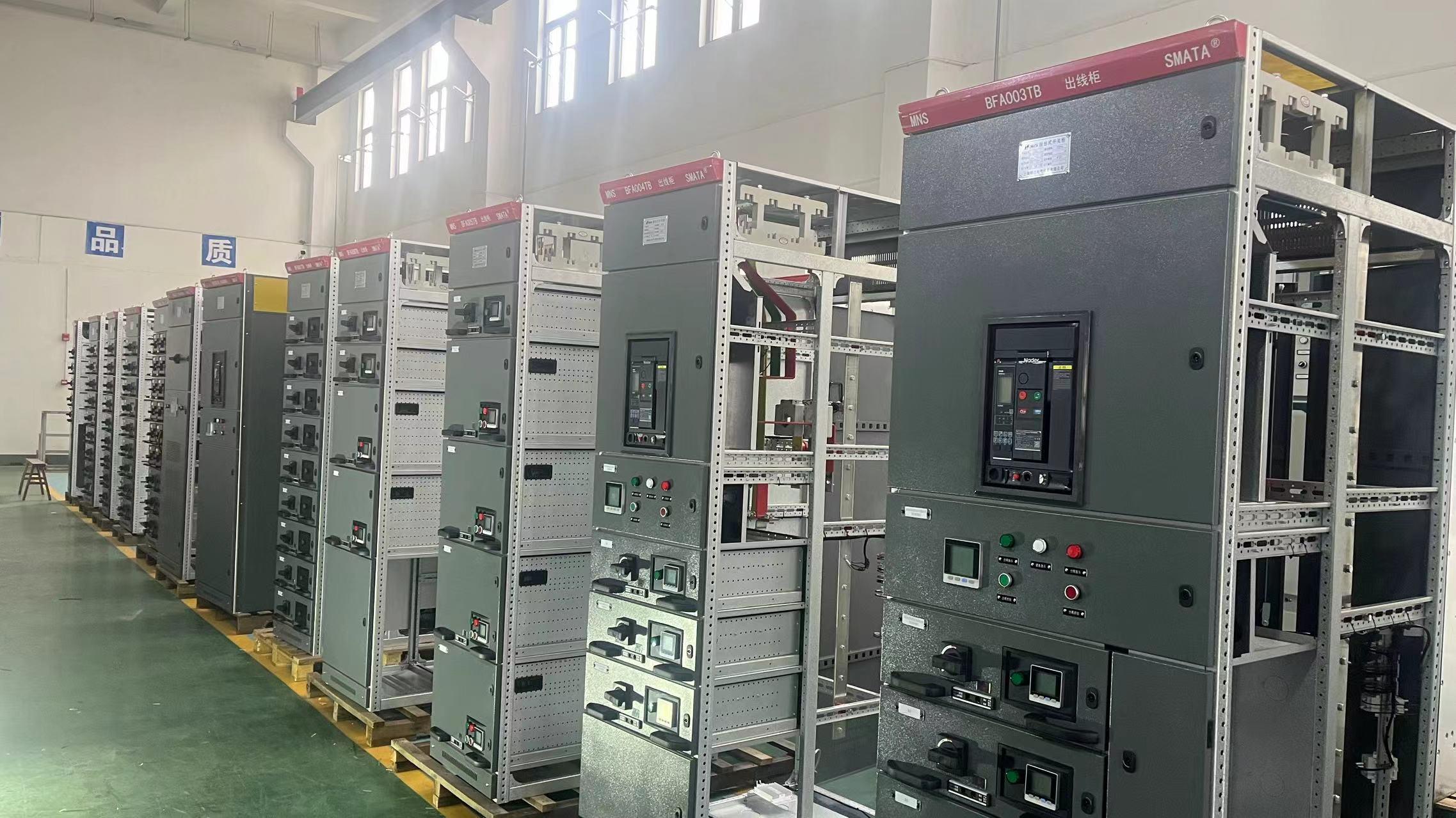
A full-size prototype reveals the mechanical and dielectric issues that stay hidden in a drawing set. For custom switchgear, busbar bending radii, joint bolt torque, and cable entry positions can look perfect on screen but clash during assembly. Testing the actual unit under power frequency withstand and lightning impulse conditions often uncovers weak points in insulation coordination that simulation packages never flag.
Heat runs on a prototype are where custom designs get exposed. Bolted joints that pass a visual inspection can show excessive temperature rise once current flows, especially with mixed conductor materials or unusual enclosure ventilation. The same applies to mechanical endurance: operating the breaker and interlock mechanisms a few hundred times will identify wear, binding, or misalignment long before any drawing review would.
Fault-condition tests add another layer drawings cannot predict. Applying a short circuit to a custom bus configuration demonstrates whether the support insulators and welded frame can absorb the magnetic forces without deformation. For arc-resistant designs, prototype arcing tests also confirm that pressure relief paths and door latches behave as intended, which is something no CAD model or tolerance stack-up can guarantee.
Busbar Cooling and Joint Design for Heavily Loaded Low Voltage Lines
In heavily loaded low voltage lines, busbar temperature rise is rarely uniform. The hottest points tend to cluster around connection interfaces where contact resistance adds to the conductor's own I²R losses. Natural convection alone often fails to keep these zones within acceptable limits, especially inside enclosures with restricted airflow. Rather than simply increasing cross-section, designers now pay close attention to surface area per unit length—ribbed or perforated profiles can shed heat noticeably faster. Vertical orientation, spacing between parallel bars, and the removal of paint or insulation at joints all influence local cooling. For continuous loads exceeding roughly 1.5 kA, passive measures may still fall short, and forced air or even liquid-cooled busways become worth evaluating.
Joint design under heavy cyclic loading has to address two competing failure modes: thermal expansion loosening and surface oxidation. A bolted overlap that looks adequate at 20°C can degrade within months if the clamping pressure drops due to differential expansion between copper or aluminum bars and steel hardware. High-torque bolts with conical spring washers help, but the contact finish is equally important—tin plating suppresses oxide growth, while silver plating offers lower resistivity but demands cleaner handling. For aluminum-to-copper transitions, bimetallic washers or clad inserts prevent galvanic corrosion that would otherwise raise resistance steeply. Some utilities now prefer welded or bolted-welded hybrid joints for long-term stability, accepting higher initial labour cost because infrared inspections reveal far fewer hot spots over the asset's life.
Busbar arrangements in low voltage switchgear also benefit from treating the whole assembly as a thermal system rather than a set of isolated parts. Heat generated at one joint can migrate along the bar and overload a neighbouring termination if the layout ignores thermal gradients. Practical field experience shows that clamping a temperature sensor only to the busbar centre gives a false sense of safety; the critical readings are at the joint edges and at the back of the bolt head. By staggering connections, adding ventilation channels under the bar supports, and specifying joint compound only where it doesn't trap moisture, designers can often reduce peak temperatures by 15–25°C without increasing copper weight. These small changes extend insulation life and reduce maintenance intervals in heavily loaded installations.
Paint, Plating, and Gaskets Decide How Long a Custom MNS Panel Lasts
A paint job on an MNS panel does more than look tidy. The right coating blocks moisture, chemical splash, and UV exposure from reaching the steel underneath. Powder coating tends to outperform wet paint here because it cures into a thicker, more uniform shell. If the panel sits in a washdown area or near salt air, a two-coat epoxy primer plus polyester topcoat will buy years of extra service life. Skip this step or choose a thin decorative finish, and rust starts creeping behind the paint within the first season.
Plating choices are just as easy to get wrong. Zinc plating with a clear passivate is fine for indoor control rooms, but outdoor installations need something tougher. Hot-dip galvanizing puts a much heavier zinc layer on the steel, and it holds up in wet, coastal, or industrial atmospheres where standard zinc flaking would leave bare metal exposed. For busbars and internal hardware, tin or silver plating matters too—not for corrosion alone, but to keep contact resistance low as oxidation tries to form on copper surfaces.
Gaskets are the quiet failure point nobody checks until water is already inside. Neoprene and EPDM both seal, but EPDM handles ozone and UV far better, so it is the safer pick for panels mounted outdoors or near electrical gear that produces ozone. The gasket needs continuous compression around the full door perimeter—any gap from a loose hinge or a bowed door frame lets dust and humidity in. Over time, a compressed gasket takes a set and loses spring. Replacing it every five to eight years, or whenever the door feels easy to close, prevents most internal corrosion and insulation breakdown.
How Your ODM Partner Handles Field Changes Without Derailing the Schedule
Field changes are an inevitable part of any hardware program, but a seasoned ODM partner treats them as a manageable variable rather than a crisis. Instead of pushing every revision through a rigid waterfall process, they maintain a rolling change review board that triages requests within 24 to 48 hours. Minor cosmetic tweaks or firmware parameter adjustments are batched and slotted into existing test windows, while more substantial alterations get a focused impact analysis covering tooling, component lead times, and certification implications. This keeps the production line humming without forcing you to choose between shipping a flawed product and missing your launch date.
What separates a truly dependable partner is their ability to quantify the ripple effect before you commit to a change. They will walk you through not just the immediate BOM cost delta, but also the hidden costs of rework, scrap, and any new validation cycles. If a connector swap means re-qualifying EMI shielding or re-running thermal tests, they say so in plain terms and present a parallel path—running a controlled pilot batch on a separate line while the main build continues with the prior revision. That kind of operational foresight means a field change doesn’t automatically mean a line-down event.
Finally, clear communication turns a potential schedule slip into a documented, agreed-upon adjustment. Rather than burying you in engineering jargon, a good ODM partner assigns a single owner for the change who updates a shared tracker daily. You see exactly which lots are affected, what inventory is being quarantined, and when the new revision will enter mainstream production. By treating field changes as an ongoing dialogue instead of a last-minute scramble, they protect your release timeline while still honoring the realities of the field.
Commissioning Checklists That Separate Working Custom MNS Panels from Paper Approvals
Typical commissioning often ends with signed checkboxes and stamped drawings, leaving custom MNS panels that pass on paper but fail under load. A checklist built for physical verification changes that: it forces torque checks on busbar joints, verifies breaker racking alignment, confirms CT polarity with primary injection, and tests interlocking logic step by step.
Rather than asking "Is the panel approved?", the checklist asks "Does the panel perform?" Each line item corresponds to a measurable action—infrared scan under load, insulation resistance at 1000V, protective relay trip times within tolerance, and actual phase rotation at the outgoing terminals. If a value isn't recorded with a meter reading or witnessed result, the item remains open.
This approach rejects the culture of paper approvals from consultants who never step onto the site. It turns commissioning into evidence-based acceptance, where custom MNS panels earn their energized status through verified performance rather than document completeness. The difference becomes obvious during first fault: a working panel responds correctly, a paper-approved panel is still being troubleshot.
FAQ
Its modular, withdrawable design lets manufacturers tailor compartments, busbar layouts, and protection schemes without compromising type-tested safety, so the final ODM build can match specific site constraints and load profiles.
Busbar current ratings, fault withstand levels, panel segmentation, ingress protection, and thermal dissipation all matter, but the real differentiator is whether the ODM can translate those specs into a buildable layout that remains serviceable under real operating conditions.
Poorly executed changes can create hot spots or reduce clearance, so a capable ODM will validate every deviation through heat-run tests, dielectric checks, and short-circuit coordination studies instead of relying on generic catalogue assumptions.
At minimum, IEC 61439 compliance should be demonstrated for the complete assembly, with clear temperature-rise verification, insulation coordination, and internal arc containment if the installation environment demands it.
Suppliers with pre-engineered MNS building blocks and local sheet-metal fabrication can compress design to delivery, while those starting from scratch or importing subassemblies often face longer cycles and more costly revision loops.
Ask whether busbar ratings and spare compartment capacity allow future breaker upgrades or additional feeders without replacing the entire lineup, and confirm the ODM can document the type-test boundaries for those extensions.
Withdrawable units, accessible cable termination zones, and clearly marked circuit identification reduce downtime during maintenance, so a design that looks compact on paper can still be a burden if technicians cannot safely isolate or replace components.
Lifecycle cost usually wins, because a cheaper ODM build that skimps on busbar sizing, corrosion protection, or component quality often leads to higher energy losses, unplanned outages, and expensive retrofits within a few years.
Conclusion
Choosing a custom MNS low-voltage switchgear ODM rarely comes down to a single specification. The layouts that actually work are the ones shaped by real floor constraints—trench positions, cable entry zones, access clearances—rather than an engineer’s ideal one-line diagram. Pushing for the smallest footprint without over-engineering means questioning every spare compartment and future tap point. Prototype testing then becomes the honest check: thermal imaging under load, short-circuit withstand on a representative section, and mechanical endurance of withdrawable units often reveal hot spots or alignment issues that clean CAD drawings never show. For heavily loaded lines, busbar cooling and joint design deserve more attention than the breaker rating alone. Proper ventilation, conservative current density, and bolted joint surface preparation keep temperature rise within limits long after installation.
What separates a dependable ODM from a one-off fabricator is how they handle field changes and final proof. Paint, plating, and gaskets are not cosmetic afterthoughts; the right coating system and IP-rated seals determine whether a panel survives humidity, dust, or chemical exposure. A strong partner absorbs late-breaking site adjustments—door swings, bus duct entry, protection relay swaps—without collapsing the production schedule, because their engineering change process is built around modular reuse and clear hold points. Commissioning then moves beyond paperwork. The checklists that matter include torque verification on every busbar joint, primary and secondary injection tests, interlock trip checks, and thermal scans at full load. Panels that pass these hands-on checks are the ones that actually keep running after the approval documents are filed.
Contact Us
Contact Person: Hellen
Email: [email protected]
Tel/WhatsApp: 86-13634205622
Website: https://www.voltcabinet.com