

IEC Standard Busbar Insulator Guide for Safe Electrical Installations
2026-11-16
Most electrical failures don't start with the obvious culprits. They begin with a busbar insulator that quietly falls out of spec. The IEC standard exists to prevent exactly that—but reading it isn't always straightforward. This guide breaks down what IEC compliance actually demands for busbar insulators in safe electrical installations, and shows how MOLDVOLT turns those requirements into practical, field-ready components.
What IEC Pollution Classes Change About Insulator Cleaning Intervals
IEC 60815 splits outdoor insulation environments into four pollution classes, from light to very heavy. The shift from one class to the next changes how quickly conductive deposits accumulate on insulator surfaces. In a light pollution area—think rural farmland or low-density residential zones—dust and salt build up slowly, so cleaning might only be necessary every few years or even on a condition-based schedule. Move to a heavy or very heavy class, such as near coastal salt spray, industrial emissions, or unpaved roads with frequent traffic, and the same insulator can develop a dangerous conductive layer within months. The standard doesn't hand out fixed calendar intervals; instead, it drives a reassessment of what “normal” contamination looks like for a given site.
Cleaning crews often underestimate how a jump from medium to heavy pollution changes the risk profile. In medium conditions, a light wash during annual maintenance may be enough to restore insulation strength. But in heavy or very heavy classes, the time between safe operation and flashover risk shrinks sharply. For example, a 33 kV line insulator near a cement plant or chemical facility might need washing every three to six months, whereas the same design in a suburban area could go two years without intervention. The pollution class effectively resets the baseline for leakage current, dry-band arcing, and surface degradation, which means the cleaning interval must be shortened not by a fixed factor but by monitoring actual equivalent salt deposit density (ESDD) and non-soluble deposit density (NSDD) trends.
Field experience shows that treating all insulators on a single calendar schedule leads to either wasted labor in clean zones or unexpected outages in dirty ones. A more practical approach uses the IEC pollution class as a starting point, then adjusts the cleaning interval based on local weather patterns, insulator geometry, and whether hydrophobic coatings are applied. In very heavy pollution areas, relying solely on periodic cleaning may be insufficient; some utilities switch to silicone rubber insulators or apply regular greasing to extend the interval from weeks to months. The key takeaway is that IEC classes are not just a specification label—they define how aggressively you need to manage surface contamination before it compromises the insulation coordination of the whole line.
Matching Busbar Insulator Creepage to Switchgear Voltage Before Installation
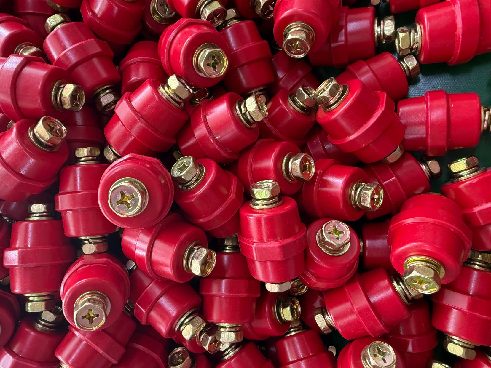
Busbar insulators often get treated as generic standoffs, but their creepage distance has to correspond to the actual operating voltage and pollution level of the switchgear. A mismatch here doesn't always show up during initial megger or hi-pot tests; it tends to surface later as tracking or flashover under humid or contaminated conditions. Before any busbar is landed, compare the insulator's rated creepage against the phase-to-phase and phase-to-earth voltage, not just the nominal system voltage. For indoor metal-clad switchgear in a clean environment, the minimum creepage might be around 12 to 16 mm/kV, but that figure shifts once you factor in dust, condensation, or coastal salt exposure.
The practical check is straightforward: get the actual creepage profile from the insulator drawing or measure along the surface from the metal end fitting to the other, not the straight-line clearance. Then divide that by the highest line-to-line voltage the gear will see. If the resulting mm/kV is below the lower band for your pollution class, don't install the busbar—even if the mechanical dimensions fit. Replacing an insulator with a longer shed or a higher creepage class before energization is a lot cheaper than pulling an arc-damaged busbar out of a live lineup later.
Mounting Distances That Prevent Flashover on Uninsulated Bus Conductors
Clearance values for bare bus bars rarely come from a single table. They shift with voltage level, altitude, humidity, and the presence of nearby grounded surfaces. A 480-volt system in a dry indoor vault may need only a few inches, while the same conductor outdoors at 5,000 feet could demand double that spacing to keep an arc from jumping. Engineers often start with basic phase-to-phase and phase-to-ground minimums, then apply correction factors for pollution or condensation. The key is to treat the gap as a living dimension, not a fixed number stamped on a drawing.
Surface condition plays a bigger role than many realize. Dust, salt film, or even a slight rounding difference on a bus edge can lower the breakdown threshold dramatically. A jagged burr or a sharp bolt head creates a high-field point where ionization begins early. That's why specifications sometimes call for larger clearances near connections and support insulators, where geometry gets irregular. It's not just about the straight runs; it's about every bracket, bend, and termination that can invite a flashover before the bus ever reaches rated voltage.
Field verification matters just as much as design intent. After installation, thermal expansion, vibration, or sag can reduce a carefully planned gap. A quick check with a laser distance meter or even a calibrated spacer bar catches problems that CAD models miss. Some crews use temporary plastic gauges cut to the required minimum, sliding them between conductors during commissioning. If the gauge binds or won't pass, the spacing is already too tight. That hands-on check often prevents the kind of arc-over that turns a routine startup into an outage.
Why Cantilevered Bus Supports Fail When Torque Specs Are Ignored
On a cantilevered bus support, every bolt carries more than its share. The mounting bracket extends outward, so the fasteners don't just clamp; they resist bending, shear, and vibration all at once. When torque specs get skipped, the joint loses its designed preload. That preload isn't a suggestion—it's what keeps the mating surfaces locked tight enough to stop micro-movement. Without it, the support starts rocking under load, and each cycle hammers the bolts a little looser.
The failure rarely happens on day one. It creeps in as galling, fretting, or a cracked weld near the base plate. Bolts stretch beyond their elastic range because nobody checked the torque wrench calibration, or worse, someone hit them with an impact gun and called it good. On a bus, road vibration turns that oversight into a fatigue crack. The support arm looks fine from the outside, but the internal stress concentration is already chewing through the metal.
What makes this specific failure maddening is how preventable it is. Torque specs exist because the engineer calculated the clamp load needed for that exact bracket geometry—not a generic guess. When a mechanic ignores them, the next inspection might find a support hanging by one thread, or the bus pulls to one side under braking because the mount shifted. The repair isn't just retorquing; it's replacing the elongated bolts and often the bracket itself, which already work-hardened into a crack. Respect the number on the print, and the support stays put for the life of the bus.
Comparing Porcelain and Polymer Bodies for High-Stress Indoor Bus Runs
Porcelain bodies have been the default choice in indoor bus runs for decades, largely because their glaze resists tracking and they hold tight dimensional tolerances under compressive load. But high-stress indoor environments rarely load a bus support in pure compression; thermal cycling, switching vibrations, and occasional short-circuit forces introduce bending and tension that porcelain handles poorly. A hairline crack in a porcelain body often goes unnoticed until a flashover or mechanical collapse occurs. Polymer bodies, typically silicone or EPDM based, shrug off those same tensile and vibration stresses due to their inherent flexibility, though they demand closer attention to creepage path design and shielding fit.
Surface behavior is another dividing line. Porcelain's smooth glaze looks ideal, yet it loses its advantage when indoor dust, humidity, and condensation combine. A conductive film can form quickly, leading to tracking and surface discharge. Polymer bodies with hydrophobic surfaces inhibit water film formation even after surface contamination, so leakage current stays lower under dirty indoor conditions. That does not make polymer bodies invincible; sustained partial discharge can erode the material if the electrical stress concentrates around metal end fittings. In high-stress indoor bus runs, that risk means the grading rings and field control must be specified more carefully than with porcelain.
Weight and installation logistics also separate the two. Porcelain bodies are heavy and unforgiving during handling, and a dropped or impacted unit can be compromised before it is ever energized. Polymer bodies weigh far less and survive typical installation knocks, but their long-term performance depends on the quality of the bonding between the polymer sheath and the fiberglass core. For high-stress indoor bus runs, the decision often comes down to which failure mode is easier to manage: sudden brittle fracture with porcelain, or gradual aging and possible tracking with polymer.
Inspecting Insulator Sheds for Hairline Cracks Without a Full Shutdown
Hairline cracks in insulator sheds often begin as nearly invisible surface fissures that can grow into flashover risks. Instead of taking a whole line out of service, crews now combine high-resolution photography, drone-mounted thermal sensors, and sensitive ultrasonic probes to scan energized insulators from a safe distance.
The trick is knowing what a healthy shed should look like on a thermal scan versus one with micro-cracking that traps moisture or creates tiny partial discharge sites. A sudden temperature differential along the shed edge, or an acoustic emission burst under mechanical load, usually warrants closer inspection with a corona camera or a robotic arm fitted with a zoom lens.
This staged approach lets utilities pinpoint only the damaged units and schedule a short, localized outage for replacement, rather than a full shutdown across the line. It also keeps inspection crews out of the most hazardous positions, since most of the data can be gathered from the ground or from a helicopter standoff.
FAQ
IEC 60664 sets insulation coordination rules, while IEC 61439 addresses low-voltage switchgear assemblies. Together they define creepage distances, clearances, and impulse withstand voltages that busbar insulators must meet for a given pollution degree and overvoltage category.
Creepage distance prevents surface tracking under polluted or humid conditions, and clearance prevents direct arc-over through air. IEC 60664 tables correlate these dimensions with working voltage, material group, and pollution degree, so an insulator is only safe when both values stay above the minimum required for the installation environment.
Use torque-controlled fastening to avoid cracking ceramic or overstressing composite insulators, mount them on flat rigid surfaces without bending the busbar, and maintain the manufacturer's specified spacing. Check that the assembled system still provides the required creepage and clearance after alignment.
Pollution degree describes how much conductive dust or moisture is expected in the location. Higher pollution degrees demand longer creepage paths or hydrophobic insulator materials, otherwise surface leakage current may cause tracking, flashover, or premature failure even if the voltage rating looks adequate.
Inspect insulators for cracks, discoloration, tracking marks, or loose hardware at intervals appropriate to the environment. Clean surfaces with a dry, nonabrasive cloth or approved solvent, and verify torque on connections. Any insulator showing mechanical damage or reduced creepage due to contamination should be replaced.
Perform a visual inspection, then apply a dielectric withstand test according to the relevant IEC test voltage for the equipment. Insulation resistance measurement with a megohmmeter can also reveal moisture ingress or surface contamination. Tests should be done with busbars de-energized and disconnected from sensitive electronics.
Using insulators with insufficient creepage for the actual pollution degree, mounting them on uneven surfaces that create mechanical stress, mixing insulator types with different thermal expansion, and over-torquing fasteners are frequent errors. Each can reduce the insulation margin below the level assumed by IEC design rules.
Conclusion
Field experience with IEC 60815 pollution classes often rewrites cleaning schedules long before the first flashover. A site classified as heavy industrial can demand insulator washing every few months, while a clean indoor substation may run for years between wipe-downs. The real hazard is assuming the old interval still applies after process changes or seasonal dust loads shift. Before mounting anything, busbar insulator creepage must be matched to the actual switchgear voltage, not just the nameplate rating, because transient overvoltages and humidity can push surface leakage well past the dry test value. Along the run, uninsulated bus conductors need generous phase-to-ground and phase-to-phase clearances derived from the insulator profile, not just the busbar spacing, to keep a stray arc from jumping across a support.
Cantilevered bus supports are a common failure point when installers treat the base bolts as ordinary hardware. IEC torque values exist for a reason: overtightening cracks the insulator flange, while undertightening lets the cantilever load shift and micro-fracture the core. For high-stress indoor runs, porcelain bodies handle compressive loads and high temperatures well, but polymer sheds tolerate impact and humidity swings with far less chipping. Both materials need periodic inspection, and hairline cracks in sheds are easy to miss during routine walk-throughs. A focused flashlight inspection at a shallow angle, plus a light tap test with a plastic mallet, can reveal fissures without de-energizing the bus or shutting down the switchgear line.
Contact Us
Contact Person: Hellen
Email: [email protected]
Tel/WhatsApp: 86-13634205622
Website: https://www.voltcabinet.com