

HIFU Transducer Supplier Selection Guide for Medical Device Manufacturers
2026-08-19
Most HIFU transducer selection guides focus on datasheets. The real risk lies elsewhere—in acoustic stack mismatches, frequency drift under load, or suppliers who disappear after the prototype phase. If you’ve ever had a transducer pass bench tests but fail during thermal cycling or long-term stability validation, you know the pain. This guide cuts through the spec-sheet noise and lays out the criteria that actually matter for medical device manufacturers: material consistency, design for manufacturability, and regulatory support. Along the way, we’ll explain why teams increasingly turn to Siansonic for custom HIFU transducers that hold up from first prototype to full production.
Why Crystal Composition Dictates HIFU Transducer Lifespan and Efficiency
The crystal at the heart of a HIFU transducer isn't just a passive component—it's the primary factor that determines how long the device lasts and how much acoustic energy it can reliably deliver. Piezoelectric materials like lead zirconate titanate (PZT) or single-crystal relaxor ferroelectrics each respond differently to the intense electrical driving fields used in high-intensity focused ultrasound. A crystal with poor mechanical quality factor or excessive dielectric loss will convert more input power into heat rather than acoustic output, gradually degrading the transducer's performance and shortening its operational life.
Composition also dictates the trade-off between bandwidth and efficiency. Single-crystal materials, for example, offer higher electromechanical coupling coefficients than conventional PZT ceramics, allowing a HIFU transducer to generate the same acoustic pressure with lower driving voltage. This reduces electrical stress on the crystal and minimizes internal heating at the focal zone. However, single crystals are often more sensitive to temperature fluctuations and mechanical clamping, so the exact dopant levels and crystal orientation must be tuned to maintain stable output over thousands of operating cycles.
In practice, transducer manufacturers adjust the crystal composition—adding elements like manganese to lower losses or using engineered domain configurations—to balance peak power handling with long-term fatigue resistance. A poorly chosen composition may work well in a benchtop prototype but fail prematurely under repeated thermal cycling or high-duty-cycle clinical use. Understanding these material-level trade-offs is essential for designing HIFU systems that maintain both efficiency and longevity without sacrificing treatment depth or precision.
Custom Acoustic Stack Design: Matching Frequency and Focal Depth to Clinical Protocols
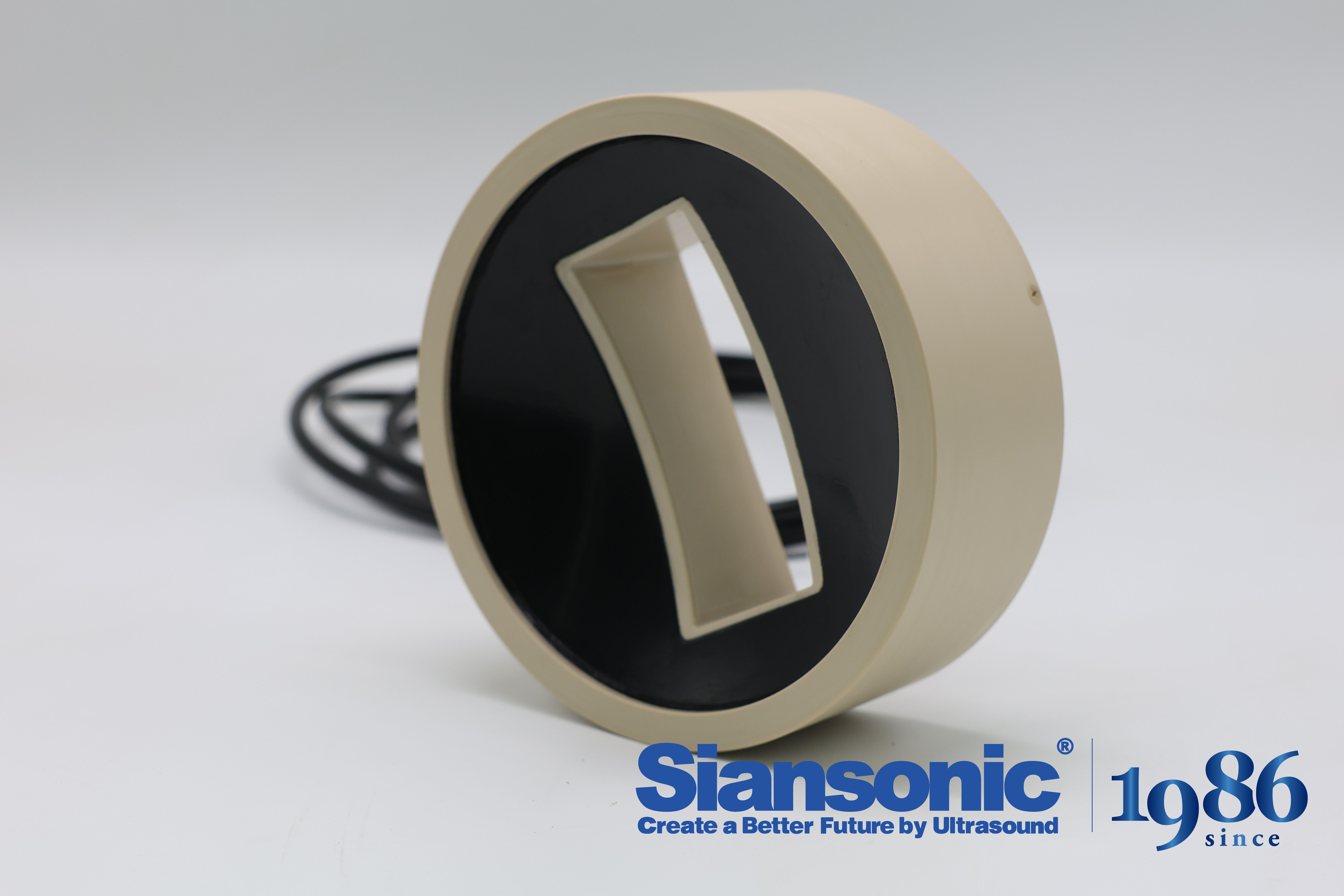
Clinical protocols rarely ask for a generic ultrasound setting. A scheme designed for superficial tendon work might require a higher center frequency and a shallow focal zone, while a deep joint treatment calls for lower frequencies and a focal point several centimeters below the skin. Custom acoustic stack design works backward from these clinical endpoints instead of forcing a clinician to adapt to an off-the-shelf transducer. By selecting a specific piezoelectric ceramic and fine-tuning the matching layer configuration, an engineer can pull the center frequency and focal depth into the exact range the protocol demands, rather than settling for a broad one-size-fits-all response.
Each layer in the stack earns its place. The piezoelectric element thickness sets the fundamental resonance, but the real flexibility comes from how the matching and backing layers are paired. Matching layers bridge the massive acoustic impedance mismatch between the ceramic and tissue, and their thickness and impedance directly shape energy transfer efficiency and usable bandwidth. The backing layer, on the other hand, controls pulse length and axial resolution. When a protocol shifts the focal depth closer to the surface, the curvature of the aperture or an acoustic lens often changes too, and the stack design has to move with those geometric adjustments. A frequent oversight is treating frequency as the only variable and ignoring focal depth. If the stack produces a pulse that loses coherence or energy before reaching the intended depth, the clinical outcome suffers no matter how ideal the frequency looks on paper.
In practice, the design loop involves finite element simulation and repeated pulse-echo testing. Frequency and focal depth from a clinical protocol are not standalone numbers; they interact with duty cycle, peak negative pressure, and tissue attenuation limits. A custom stack allows the entire acoustic field to be optimized for one coherent set of clinical parameters, rather than asking the clinician to compensate for hardware compromises. The goal is a transducer that converts electrical drive into focused acoustic energy precisely where the treatment plan says it should land, which means every layer's thickness, sound speed, and attenuation have to be weighed against each other, not copied from a previous design.
Regulatory Documentation and Biocompatibility Testing You Can't Afford to Overlook
Early device development often treats biocompatibility as a final approval hurdle, but the regulatory file starts taking shape long before any formal submission. Mapping every patient-contacting material to the relevant ISO 10993-1 endpoints at the design freeze stage prevents cascading delays later. When chemical characterization data is missing or extractables studies skip a processing aid, reviewers tend to ask for additional justification that can add months to a timeline.
The weak link in many submissions is not the absence of test data but the inability to connect that data to the exact device configuration under review. Test reports should reference the particular manufacturing lot, sterilization method, and clinical contact duration. If a supplier shifts a resin grade or colorant after biocompatibility work is complete, the original report loses much of its weight unless a documented rationale or delta testing follows. A living gap analysis that links each biological endpoint to a specific report number and revision keeps the file audit-ready.
Regulatory expectations have moved well beyond a simple cytotoxicity and sensitization panel. Chemical characterization under ISO 10993-18 and toxicological risk assessment under ISO 10993-17 are now baseline expectations for many device categories, especially under the EU MDR. A concise biological evaluation plan paired with a thorough report often means the difference between a short clarification round and a formal deficiency letter.
Production Capacity and Lead Time Commitments That Survive Real Demand Spikes
Most production schedules fall apart the moment a real demand spike arrives, because they're built on smoothed forecasts and average throughput. When orders jump 40% in a week, the hidden queues appear: shared equipment becomes a bottleneck, supplier deliveries slip, and the promised lead times quietly stretch from days into weeks. A capacity plan that survives these moments has to be designed around peak capability, not normal operating levels. That means keeping a margin of unused capacity — extra shifts, cross-trained operators, or modular lines — that can be activated without hiring or retooling. The margin looks wasteful on a spreadsheet, but it's the only thing that keeps lead times honest when demand stops behaving.
Lead time commitments need to be recalculated in real time against actual load. A fixed 'ships in 5 days' promise is a liability if the shop floor is suddenly buried. Instead, let the system show available slots based on current work-in-progress and material availability, then hold those slots only for confirmed orders. This shifts the conversation from 'we missed your date' to 'here's the earliest reliable date we can commit to right now.' Customers may not love a longer lead time during a spike, but they'll trust a date that doesn't slip.
The only way to know if capacity and lead time promises will hold is to stress-test them. Run simulation exercises where demand doubles for two weeks and watch where orders pile up, which supplier breaks first, and how quickly the team can recover. Build contingency agreements with secondary suppliers that can ramp up on short notice, even if their unit cost is higher. And be transparent with customers before the spike hits: state clearly which products are made to order, what the current load is, and when the next available production window opens. Real demand spikes punish optimistic assumptions; they reward operations that plan for the surge.
Co-Engineering Support: From Prototype Iterations to Field Failure Diagnostics
Co-engineering here starts before the first board spins. We sit with your design team during schematic reviews, flagging marginal timing paths and component derating issues that usually surface only after prototypes are built. Once hardware arrives, we handle the messy iteration loop: swapping load resistors to chase a startup inrush problem, modifying gate drive traces to kill a 14 MHz oscillation, or rewriting a sensor polling routine that occasionally locks up at -20°C. Each change gets validated on the bench with the same test sequence your production line will use later, so surprises don't migrate downstream.
The same engineers who debugged those early prototypes also work on field returns. When a batch of units fails after six months in humid environments, we start with the returned boards, but we don't stop at replacing the obviously corroded connector. We pull assembly records, check solder paste lot numbers, and compare failure locations against thermal images captured during qualification. Sometimes the root cause is a changed conformal coating process; other times it's a firmware state that only appears after a specific power-cycle sequence. We document the findings with enough detail that your contract manufacturer can adjust immediately, and we stay involved through the re-qualification run to confirm the fix holds.
The Hidden Cost of Inconsistent Transducers in High-Volume Medical Device Production
Every line stoppage that traces back to a transducer reading slightly out of spec feels minor in isolation. A calibration tweak here, a rejected batch there. But across a quarter of a million units, those small variances compound into a quiet drain on yield that rarely shows up on a standard cost-per-part dashboard. Quality engineers get pulled away from preventive work to chase intermittent signal drift. Production supervisors start padding schedules with buffer time for re-testing. The transducer itself might cost a few dollars. The hidden line item is the cumulative labor, scrap, and delayed shipments that no purchase order ever captures.
What makes this especially dangerous in high-volume medical device manufacturing is that the acceptable tolerance window isn't just a suggestion from the datasheet—it's often tied to patient safety or regulatory clearance. A pressure transducer that drifts by 2% may still pass incoming inspection if the test is done at room temperature and low cycle count. But after ten thousand actuations inside a warm, humid assembly environment, that same drift can push a final device outside its validated performance envelope. By then, the batch is already built, and the real cost isn't just the transducer; it's the containment, the root cause investigation, and the awkward conversation with the notified body about why your process capability index looked fine on paper.
The pragmatic fix usually isn't a more expensive sensor—it's tighter incoming lot control and real-time trend monitoring at the point of use. Some contract manufacturers now sample transducers under simulated production load, not just static bench conditions, and feed that data back to the supplier weekly. Others have moved away from single-source procurement for critical sensing components, not because the primary vendor is bad, but because having a second source forces both suppliers to hold their process variation to a level that keeps the whole line predictable. The hidden cost stops being hidden when you start treating every inconsistent transducer as a signal that your measurement system—not just your device—is out of control.
FAQ
Focus on center frequency, bandwidth, acoustic power output, focal geometry, and electrical impedance matching. A dependable supplier will provide detailed test reports for each batch, not just nominal datasheet values. Ask for actual measured data under operating conditions, including thermal stability and long-term duty cycle performance.
Look for ISO 13485 as the baseline. Depending on your target market, the supplier may also need FDA registration, CE marking under MDR, and compliance with IEC 60601-1 for electrical safety. More importantly, confirm they follow documented process validation for transducer assembly, including cleanroom controls if needed.
Request a detailed acceptance test procedure that includes hydrophone scans, field mapping, and pressure amplitude verification. A trustworthy supplier will offer lot-level traceability and show statistical process control charts for key acoustic parameters. Consider asking for a pilot batch before committing to volume orders.
Beyond standard off-the-shelf designs, a strong partner will support adjustments in frequency, focusing depth, aperture size, and housing materials. They should work with your team on thermal simulation, matching network design, and cable strain relief. Ask about their in-house prototyping turnaround time and whether they keep a library of previously validated custom designs.
Review their component sourcing strategy, especially for piezoelectric ceramics and backing materials. A reliable supplier maintains safety stock or dual sourcing for critical raw materials and provides a written obsolescence plan with minimum notification periods. You can also ask to see their recent capacity expansion or audit reports.
Expect comprehensive user manuals, assembly instructions, sterilization compatibility data, and material certifications. The supplier should offer direct access to application engineers for integration troubleshooting, not just a generic support ticket system. Ask for typical response times and whether they provide on-site assistance during prototype build and verification.
Bring them in during the feasibility phase, before finalizing your acoustic window and housing design. Early collaboration prevents costly redesigns related to impedance mismatch, thermal management, or focal length adjustments. A good supplier will contribute to design reviews and help define acceptance criteria that align with your clinical performance goals.
Be cautious of suppliers that cannot provide third-party test data, have unclear cleanroom practices, or rush to quote without asking about your intended use conditions. Other warning signs include vague lead times, no evidence of customer references in medical applications, and unwillingness to share a failure analysis process. Trust is built on transparency, not just price.
Conclusion
Selecting a HIFU transducer supplier starts with material science, not marketing claims. The piezoceramic or composite crystal directly determines how long the element holds its electroacoustic efficiency under repeated thermal and mechanical stress, so demand batch-level impedance curves and aging data rather than nominal specs. Then examine the acoustic stack: a supplier that simply offers off-the-shelf focal lengths often cannot match the pulsing protocols your clinical application requires. Request a design review that maps frequency, matching layers, and lens geometry to the exact focal depth and lesion shape you intend to achieve. Equally important is the paperwork that proves safety. Regulatory documentation should cover ISO 10993 biocompatibility for patient-contact materials, sterilization compatibility, and traceability of every component. If a vendor pushes back on sharing raw test reports or material certificates, treat that as a disqualifier before you ever evaluate samples.
Once a design passes technical review, shift focus to manufacturing reality. Production capacity claims mean little without documented surge history; ask how the supplier handled a 40% volume spike in the past and whether their lead times survived it. Co-engineering support matters after delivery too. A supplier willing to join prototype iterations, refine assembly fixturing, and analyze field failures gives you a partner, not just a parts source. Finally, quantify the hidden cost of inconsistency. In high-volume production, even small variations in acoustic output or focal geometry across transducers force extra calibration, raise scrap, and erode clinical confidence. Compare suppliers using process capability indices and ongoing lot-to-lot SPC data, because the cheapest quote often becomes the most expensive warranty burden.
Contact Us
Contact Person: Ivy Zhang
Email: [email protected]
Tel/WhatsApp: +86 1081502288
Website: https://www.siansonic.com/