

Copper-Nickel-Chrome Barrel Plating Equipment Manufacturer Guide to Quality and Efficiency
2026-11-02
Barrel plating lines for copper-nickel-chrome deposits demand more than just hardware—they require a balance of throughput, solution control, and part coverage that most suppliers overlook. As a manufacturer focused on these exact challenges, Junda has built its reputation on turning quality and efficiency from buzzwords into measurable outcomes. This guide walks you through the critical design and operational factors that separate a reliable barrel plating system from one that underperforms, so you can avoid costly rework and keep your line running at full capacity.
Beyond Surface Shine: How Barrel Geometry Shapes Plating Uniformity
Plating uniformity in barrel processing rarely comes down to chemistry alone. The shape and internal contours of the barrel itself dictate how parts tumble, how current reaches recessed areas, and where solution flow stagnates. A cylindrical barrel with flat ends, for instance, creates predictable but uneven mixing near the corners, often leaving those areas with thinner deposits. By contrast, a hexagonal or octagonal barrel forces more aggressive part turnover, breaking up shadowing effects and letting fresh electrolyte reach every surface.
Even small changes in geometry alter the electrical field distribution. The distance between the anode and the rotating load varies constantly, but a barrel with tapered or angled perforations can smooth out those fluctuations. Openings that are too large dump solution and reduce contact time, while tiny holes starve the innermost parts of fresh ions. Barrel ribs or internal baffles, though rarely mentioned in basic guides, redirect the tumbling pattern so that heavy parts don't settle into a static clump at the bottom. That clumping is the single biggest cause of non-uniform thickness in barrel plating.
Operators chasing a brighter finish often focus on brighteners and levelers, yet the barrel's shape quietly determines whether those additives ever reach the part uniformly. A well-designed barrel doesn't just shine the outer layer; it equalizes exposure time, current density, and solution exchange across the entire load. When plating specs push beyond cosmetic gloss into functional thickness tolerances, ignoring barrel geometry means fighting the process instead of working with it.
What Separates a Durable Plating Line from a Costly Downtime Trap?
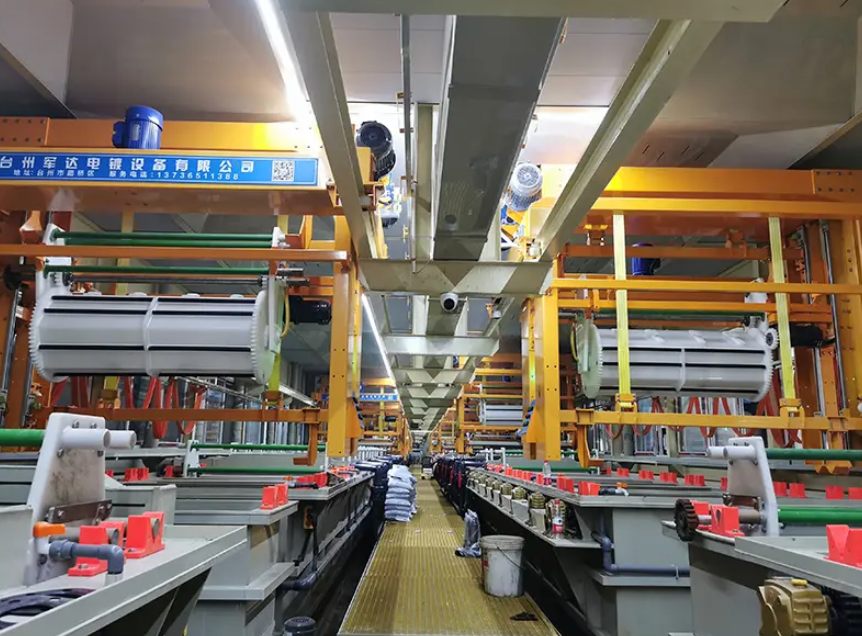
Most plating lines look fine on paper. Pumps rated for the right flow, tanks sized correctly, rectifiers within spec. Yet some facilities run for a decade with only minor touch-ups, while others bleed money through unplanned stoppages every few months. The difference rarely shows up in the original equipment list. It hides in how the line handles thermal cycling, chemical creep, and the slow corrosion of parts that never get inspected until they fail.
A durable line earns its reputation through small, deliberate choices. Frame materials that resist the specific acid mist in your shop, not just generic stainless. Bus bar connections torqued and coated to survive constant expansion and contraction. Walkways and drip pans designed so a leaking hose doesn't cascade onto a rectifier below. These details don't appear in glossy brochures, but they determine whether your maintenance crew spends Saturdays fixing or fishing.
The costly downtime trap often starts with a single overlooked joint or a sensor that was never re-ranged after a chemistry change. Once one component fails, the ripple effect hits rinse quality, plating thickness, and eventually your delivery schedule. A truly durable line isn't just built to run; it's built to be repaired quickly when something inevitably gives, with isolation valves and access panels placed where a technician can reach them without draining half the system. That's what separates a workhorse from a recurring headache.
Fine-Tuning Current Density Without Guesswork
Instead of leaning on intuition or fixed templates, fine-tuning current density begins with capturing the actual distribution across the conductor. A few strategically placed sensors or a thermal map reveal exactly where the current crowds, and that local data becomes the baseline for every later adjustment.
From there, small deliberate changes—altering pad geometry, adjusting trace width, or shifting via placement—are tested one at a time. Each iteration is compared against the measured baseline, not a generic design rule, so the tuning process stays grounded in what the board actually does.
The final step is verification under load. By ramping up current in controlled steps and watching for hot spots or voltage sag, you confirm that the tuned density holds across operating conditions. This closes the loop between modification and measurement, removing the guesswork that usually creeps into high-current layouts.
The Hidden Chemistry of Consistent Nickel Deposition
Most plating lines treat nickel deposition as a steady-state process, but the actual chemistry at the cathode surface is anything but static. During reduction, hydrogen evolution raises the local pH inside the diffusion layer, even when the bulk bath reads a stable 4.0. This subtle shift is enough to precipitate nickel hydroxide species that co-deposit with the metal, creating a dull, stressed, or brittle layer. Boric acid does far more than buffer the tank—it short-circuits that interfacial pH spike by acting as a weak acid carrier, releasing protons right where they are consumed. Ignoring this hidden buffer role is a common reason two baths with identical bulk chemistry produce noticeably different deposit consistency.
Additive behavior adds another layer of concealed complexity. Brighteners, carriers, and levelers do not simply “improve” the deposit; they compete for adsorption sites and respond to local current density in uneven ways. A brightener molecule that suppresses growth at high-current edges may be consumed faster near sharp corners, while a carrier can accumulate in low-flow recesses and block brightener access. The result is not a simple average of their effects but a shifting balance that depends on agitation pattern, part geometry, and even the age of the bath. Decomposition products from organic additives accumulate slowly and change polarization behavior, so a bath that ran perfectly on Monday can produce cloudy or pitted work by Friday—without any change in the nominal additive concentration readings.
The anode side is equally hidden from routine inspection. Nickel anodes do not dissolve with 100% efficiency, and the ratio of anode to cathode current density shifts as the anode surface passivates or roughens. Chloride ions help maintain active dissolution, but they also oxidize organic additives at the anode, producing breakdown compounds that migrate to the cathode and alter nucleation. Trace metallic impurities—copper, iron, zinc—enter from parts, racks, or water, and even a few parts per million can displace nickel at the cathode or trigger pitting. Consistent nickel deposition therefore depends less on a single parameter and more on controlling these interacting, slowly drifting variables: interfacial buffering, additive byproduct accumulation, anode condition, and trace metal load.
Operator-Friendly Controls That Prevent Batch-to-Batch Drift
Most batch inconsistencies trace back to tiny setting changes made between runs—someone nudges a temperature dial, re-enters a mixing time, or bypasses a step because the interface makes it hard to see what was used last time. The fix starts with controls that treat every adjustment as a deliberate act. Recipe parameters live in a locked digital sheet tied to the product code, so operators aren't retyping values from memory. When a deviation is required, the system asks for a reason code and logs who changed what, creating a visible trail that discourages casual tweaks.
Visual cues matter more than extra training. If the display highlights only the next required action and hides options that don't apply to the current recipe, there's far less room for improvisation. Ranges are enforced at the point of entry, not after the fact—if a setpoint falls outside the validated band, the control refuses the input and offers the closest acceptable value. This keeps individual operator habits from slowly shifting a process over multiple shifts, while still giving supervisors enough flexibility to authorize necessary exceptions without breaking the baseline.
Scaling Up Copper-Nickel-Chrome Lines Without Sacrificing Finish Quality
Ramping up copper-nickel-chrome plating output often exposes the weak points in a line that once seemed stable. The first casualty is usually finish consistency: thicker deposits start to hide micro-surface defects, nickel brighteners drift out of balance, and chrome rinses leave faint haze when racks move faster. Instead of pushing more amps blindly, operators gain more by tightening pre-plate cleaning and activating steps, because at higher throughput any residual oil or oxide becomes magnified in the final nickel layer. Keeping the copper strike uniform and slightly thicker at high current density zones prevents the nickel from exaggerating uneven base metal polish.
Chemical control shifts from routine top-ups to demand-based replenishment once production scales. Nickel brightener and wetter consumption do not rise linearly with amp-hours if the bath temperature, air agitation, and anode area are not adjusted together. Running a pilot rack with the same part geometry before full ramp-up reveals where chrome thickness may build at edges or thin out in recesses. Small changes such as repositioning anodes, adding shields, or reducing rack density in high-current areas preserve reflectivity without slowing the whole line.
Rinse quality becomes a hidden bottleneck when line speed increases. Drag-out from nickel into chrome rises with faster transfer, and even trace contamination dulls the chrome finish or creates white staining. Counterflow rinses, short drain times over the process tank, and periodic conductivity checks keep rinsewater clean enough to match the higher part volume. Rather than accepting a slight drop in gloss as inevitable during scale-up, the most successful lines treat finish quality as a controllable variable and adjust mechanical, chemical, and rinsing parameters in parallel.
FAQ
Look closely at barrel perforation design and solution transfer. Poor hole patterns trap chemistry or cause uneven deposit distribution, especially on small parts. Ask the manufacturer for sample trials with your actual components before signing off.
Mix load size, rotation speed, and current density. Overloading a barrel hides parts from the cathode contact and creates shadowing. A variable speed drive and segmented danglers help bring thickness variation down to a repeatable range.
Drag-out control makes the difference. Well-placed spray rinses, drain boards, and return drains cut cross-contamination between copper, nickel, and chrome tanks. This keeps the baths cleaner longer and reduces chemical corrections.
Check dangler contacts and barrel doors every shift. Worn contacts cause arcing and poor plating, while loose doors leak parts. A five-minute inspection saves hours of rework and lost production.
If your part mix changes often, modular tanks and rectifiers give flexibility without rebuilding. A fully custom line suits high-volume dedicated parts. Ask the manufacturer to show past layouts for similar work.
High ripple disturbs nickel and chrome deposition, leading to dull or stressed deposits. Specify a rectifier with low ripple, ideally under 5%, and verify it under your typical barrel load, not just open circuit.
Use shielded danglers and avoid excessive current density. Chrome requires careful anode placement and solution agitation. A good barrel design rotates parts out of high-current zones quickly to prevent burning and whitewash.
Ask for documented test data from similar parts, including thickness distribution, plating speed, and chemical consumption. A reliable supplier will run trials, share bath analysis schedules, and offer training for your operators.
Conclusion
A dependable copper-nickel-chrome barrel plating line relies on more than bright deposits and polished marketing claims. Barrel geometry directly controls how parts tumble, drain, and receive current, so perforation patterns, flight design, and barrel diameter all influence plating uniformity before the first layer bonds. Pair that with a rectifier setup that lets operators fine-tune current density through real ramp profiles and workpiece surface area calculations, and you remove the guesswork that causes burning, shadowing, or thin nickel edges. The chemistry side matters just as much: consistent nickel deposition depends on additive replenishment tied to amp-hours, not calendar days, along with tight control over pH, temperature, and chloride levels to prevent passivation and roughness.
Beyond the tank, a durable line separates itself by how it handles loading, maintenance access, and control repeatability. Quick-release danglers, robust barrel gears, and corrosion-resistant saddles reduce unexpected downtime, while operator-friendly controls with recipe lockouts and automatic bath sampling keep batch-to-batch drift from creeping into production. For manufacturers scaling up copper-nickel-chrome capacity, the surest path is modular plating cells and shared filtration/rectifier redundancy, so increased throughput never forces a compromise on chrome haze, nickel leveling, or copper coverage. The result is equipment that stays productive under high mix and high volume, not just during a demonstration run.
Contact Us
Contact Person: hayyr
Email: [email protected]
Tel/WhatsApp: 8613082110525
Website: https://www.jundaelectroplating.com