

Cleanroom Facility Factory Design and Construction Best Practices
2026-08-16
When a cleanroom facility is designed without a deep understanding of airflow, material compatibility, and operator workflow, even the most advanced pharmaceutical process can fall short. At GENO Pharmatech, we see too many projects where construction shortcuts create contamination risks that only surface during validation. This guide distills the best practices that actually matter — from layout zoning and pressure cascade design to finishes and commissioning — so you can avoid costly rework and build a cleanroom that performs from day one. Whether you are upgrading an existing suite or planning a greenfield facility, the following principles will help you align design intent with operational reality.
Flooring Decisions That Make or Break Cleanroom Viability
In cleanroom environments, the floor is not just a surface—it is the first line of defense against contamination. The wrong material can shed particles, harbor microbes, or react with cleaning agents, quietly undermining the entire controlled space. A floor that seems durable in a showroom might fail within months under the constant assault of disinfectants, heavy carts, and electrostatic discharge requirements.
Designers often overlook how floor seams and transitions become invisible highways for contaminants. Even a premium vinyl or epoxy system can fail if the installation leaves micro-gaps at the cove base or around drains. The decision to use heat-welded seams versus chemical bonding, or to pour a seamless terrazzo versus laying tiles, directly determines how many crevices exist for bacteria to colonize.
Static dissipation adds another layer of complexity. A floor that meets resistance specifications at installation can drift out of compliance as humidity fluctuates or as conductive fibers wear away. The most successful cleanroom floors are chosen not just for their initial certification but for how consistently they perform after years of aggressive mopping, rolling loads, and thermal cycling.
Airflow Design That Delivers Laminar Flow Where It Actually Matters
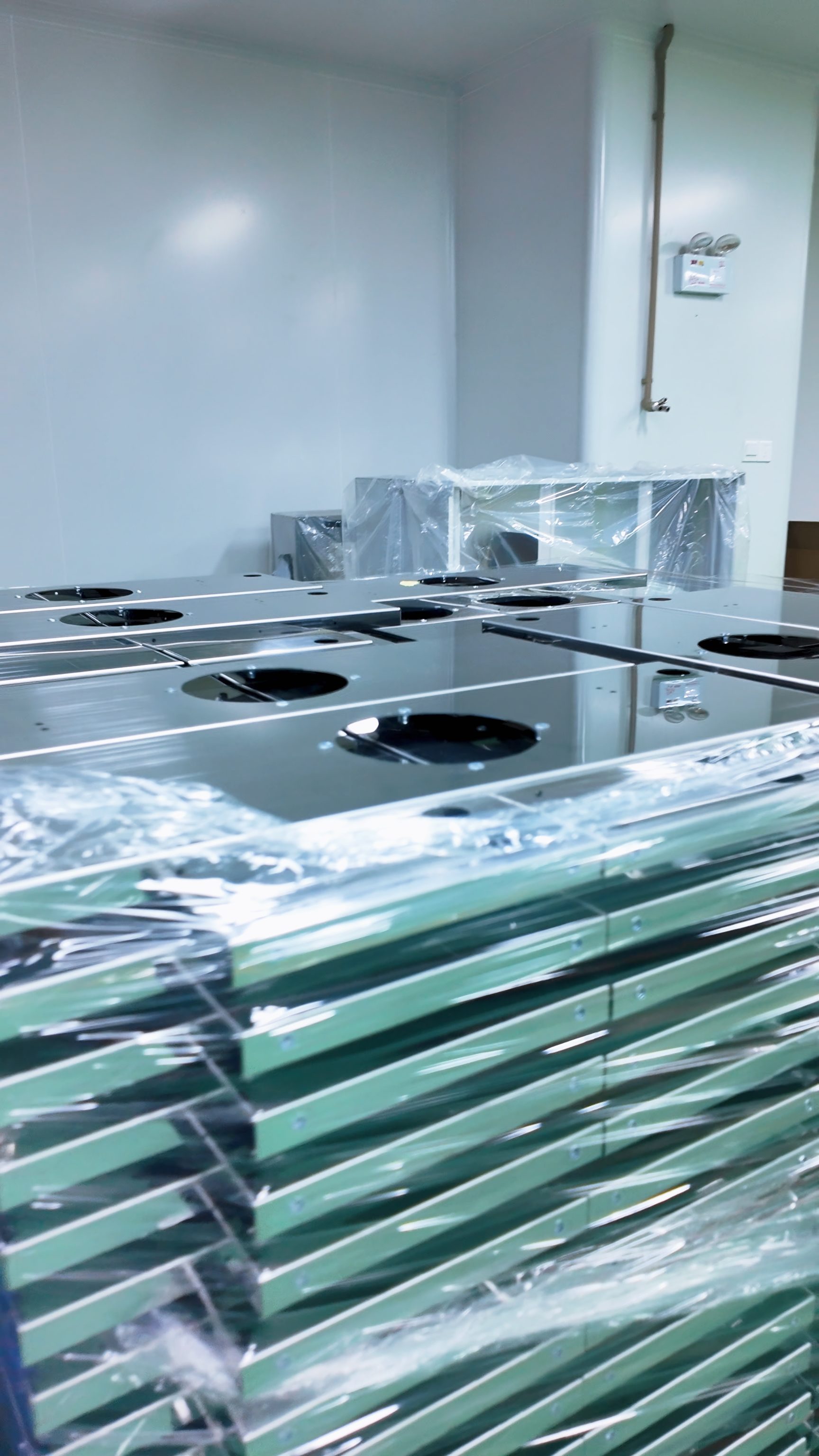
Most airflow systems chase uniform velocity across an entire space, but that often means laminar flow gets wasted on areas where it has little impact. This design focuses on directing a stable, low-turbulence stream exactly where breathing zones, work surfaces, or sensitive processes are located. Instead of filling a whole room with gentle air movement, the system shapes the flow path around what actually needs protection.
The result is a quieter, more energy-efficient setup that doesn't sacrifice performance. By mapping local airflow patterns and adjusting outlet geometry, the design maintains clean, uninterrupted layers of air right at the point of use. Whether it's keeping particulates away from a patient or preventing cross-contamination on a lab bench, the emphasis stays on functional zones rather than blanket coverage.
In practice, this approach also simplifies maintenance and reduces filter load, because the volume of air that must be kept laminar is smaller. Contaminants are pulled away from critical regions before they can disperse, and the system adapts more easily to real-world layouts where walls, equipment, and people inevitably disrupt ideal flow patterns.
Material Specs That Stop Particle Shedding Before It Starts
Controlling particle shedding isn't about adding more filtration downstream—it's about engineering the material so particles never break free in the first place. For cleanroom consumables, medical device components, and semiconductor handling tools, the real difference comes from specifications that target the root cause: weak surface integrity under mechanical stress. A material with a low coefficient of friction alone won't help if its surface layer is brittle. What matters is the combination of low surface energy, controlled crystallinity, and a manufacturing process that leaves no loose fines or micro-burrs. When those specs are dialed in, the material resists abrasion and flex fatigue without generating debris, even after hundreds of use cycles.
Key specifications to demand include a maximum surface roughness (Ra) below 0.4 microns, a shore hardness matched to the application's flex requirements, and a static dissipative range that prevents charged particles from clinging then releasing. For polymer-based materials, specifying a high molecular weight with narrow polydispersity reduces low-molecular-weight species that can migrate and shed. Add to that a post-curing or annealing step that relieves internal stress and you get a surface that doesn't craze or spall under repeated contact. These aren't arbitrary numbers—they come from accelerated wear testing that simulates real-world use, such as rotary abrasion per ISO 5470 or flex testing per ASTM D2176, where pass criteria are measured in particles per square centimeter rather than visual inspection alone.
The payoff shows up in dynamic particle counting during simulated operations. For instance, a polyurethane tubing spec that caps extractable particles at 50 per milliliter under ISO 10993-12 extraction protocols will shed far less than a generic tubing that meets only dimensional tolerances. Similarly, a cleanroom wiper with a knitted polyester structure and laser-sealed edges—specified by edge particle count below 10 particles per linear meter at 0.5 microns—prevents fiber release from the start. These material specs turn particle control from a cleanup problem into a design requirement, eliminating the need for redundant cleaning steps and reducing contamination risk in critical environments.
Construction Sequencing That Keeps the Build From Contaminating the Room
One of the more effective moves is to split the job into "dirty" and "clean" zones before a single tool comes out. Demolition, cutting, and mixing happen on the dirty side, while the finished or occupied side gets sealed off with zip walls and negative air pressure. That pressure difference keeps dust and fumes from drifting back into spaces that are already in use, and it forces you to think through the order of operations instead of letting crews wander through finished areas with muddy boots.
The sequence itself matters far more than most people assume. For example, rough openings should be cut and framed before new finishes go in, and any work that produces airborne particles—grinding concrete, sanding drywall, spraying texture—should wrap up before final cleaning starts. If a trade needs to pass through a completed room, the path gets covered with ram board and the door gets taped off, but ideally the schedule keeps those crossings to a minimum.
A practical rule is to build from the farthest point outward, so workers and materials don't have to travel back through areas that have already been cleaned or commissioned. Temporary barriers get inspected at the start of each shift, and air scrubbers run continuously in the buffer zone. Small details like staging a sticky mat at the exit and swapping out boot covers between zones might seem fussy, but they are often the difference between a room that stays spotless and one that needs a complete re-clean before handover.
Pressure Cascade Adjustments That Protect Critical Zones
Pressure cascades don't fail uniformly—they concentrate stress at the weakest points, often where operators least expect it. The most effective adjustment strategy starts by mapping critical zones under varying load profiles, then deliberately staging relief points so that pressure bleeds off before it reaches sensitive equipment. Instead of a single broad setpoint change, we favor a stepped cascade: slight upstream reductions that accumulate into meaningful downstream protection, while preserving throughput where it matters.
One overlooked lever is the timing of valve responses. Fast-acting relief valves can overshoot and create transient spikes that hammer seals and instrumentation. Slowing the response curve—via pilot-operated regulators or restricted orifices—lets the system absorb pressure waves gradually, protecting critical zones without starving the process. The key is to tune both the magnitude and the rate of each cascade stage, not just the final target.
Field data often reveals that critical zones fail not from steady-state pressure, but from repeated micro-cycles during start-up and shutdown. Adjusting the cascade to include a brief pre-charge phase—where pressure climbs in a controlled ramp rather than a sharp step—can eliminate most fatigue-related leaks. It's a small change in sequence, but it shifts the burden from components to the control logic, where it's far easier to manage.
Commissioning Checks That Catch Problems Before Validation Day
Waiting until validation day to discover a wiring fault or a misconfigured sensor turns a routine sign-off into a fire drill. Smart teams front-load their commissioning checks with targeted inspections that expose weaknesses while there's still time to adjust. One overlooked pressure switch or an improperly seated terminal can cascade into hours of troubleshooting, so the focus stays on the interfaces and settings most likely to drift during installation.
Start with loop-by-loop verification of every analog input against a known source, not just a quick glance at the HMI. Compare expected millivolt or milliamp values with field measurements and record the offset. Then cycle each digital output in forced mode while a second person watches the physical device—relays click, valves shift, and indicator lamps confirm what the software claims. This catches reversed polarity, swapped channels, and sticky actuators before they become validation failures.
Finally, simulate the worst-case alarm sequence with critical interlocks bypassed one at a time, then restore them and confirm the system returns to a safe state without manual resets. Pay particular attention to communication timeouts and redundant controller failovers, because these rarely show up during normal operation but often dominate post-validation punch lists. The goal is not to prove everything works, but to find what still needs attention when the cost of fixing it is lowest.
FAQ
Undersizing the air handling system remains a frequent issue. Many projects base HVAC capacity on ideal occupancy and equipment loads that later expand, leading to pressure cascade failures. Another overlooked aspect is the placement of return air grilles; if they sit too high or too close to supply diffusers, short-circuiting prevents proper particle flushing. Designers should also avoid routing utility piping through clean zones without sealed penetrations, since each unsealed penetration becomes a contamination pathway.
The finish needs to survive repeated chemical exposure without micro-cracking, because even hairline cracks harbor microbes and shed particles. For walls, factory-applied fiberglass-reinforced plastic panels with heat-welded seams outperform site-painted gypsum in most wet or high-sanitation environments. Flooring choices often come down to sheet vinyl versus epoxy terrazzo; epoxy terrazzo costs more initially but resists forklift traffic far better, reducing future shutdowns for patching. Whatever the material, mock-up testing with the actual cleaning agents is essential before full installation.
Filter integrity testing after the facility reaches operating temperature is sometimes rushed or skipped, yet thermal expansion can unseat HEPA filters installed in cooler conditions. Room pressurization should be tested with all doors closed and airlocks in normal operation mode, not just with temporary conditions. Lighting and equipment heat loads also need to be active during airflow visualization, otherwise the smoke studies do not reflect real-world thermal plumes. Documenting these tests under full load conditions gives a far more reliable baseline.
Instead of just lowering air change rates, focus on recovering energy from exhaust air and using variable speed drives on recirculation fans. Demand-controlled filtration adjusts fan speed during low-production periods while maintaining required particle counts. High-efficiency motors and LED lighting reduce internal heat gains, which in turn cuts cooling load. The key is to design for part-load operation from the start, because cleanrooms rarely run at full occupancy and equipment load around the clock.
They act as staged transition zones that let pressure differentials do the heavy lifting. A properly designed airlock prevents direct door openings between the factory floor and the cleanroom, so particles don't get pulled in when someone enters. Gowning rooms should be laid out with a clear separation between street clothes and cleanroom garments, often using a bench as the dividing line. The pressure cascade from gowning room to airlock to cleanroom should never be reversed, and each door needs an interlock to avoid simultaneous opening.
Ask for a detailed sequence of construction activities, because cleanroom protocols must begin before the final finishes are installed. Find out who is responsible for sealing every penetration through walls and ceilings, and request a log of those penetrations. Clarify how the contractor will handle temporary construction dust, including negative air machines and sticky mats at exits. Finally, request references for similar factory projects where the cleanroom passed certification on the first attempt, not after months of rework.
An ISO 8 space can often rely on turbulent dilution with moderate air change rates, while ISO 5 and below usually require unidirectional flow and much higher air volumes. The tighter the classification, the more important ceiling coverage becomes: an ISO 5 room may need nearly full-ceiling HEPA filtration, while an ISO 7 room can use strategically placed terminal filters. Wall and floor finishes also need more frequent cleaning and greater chemical resistance as classification increases.
Conclusion
A cleanroom is only as dependable as the surfaces beneath it and the air moving through it. Flooring choices ripple across every stage of operation: a seamless, chemical-resistant sheet vinyl or epoxy system with heat-welded seams prevents cracks where microbes and particles collect, while any slight unevenness disrupts wheeled cart traffic and creates abrasion dust. Equally important is airflow design that doesn't just chase a certification number but places laminar flow exactly where open product handling occurs. Too often, designers over-pressurize the entire suite and neglect local low-velocity return paths near critical workstations, which leaves dead zones even when average air changes look impressive. Material specifications then compound these effects. Surfaces that shed—some powder-coated metals, unfinished ceiling tiles, or gasketing that degrades under repeated cleaning—can quietly undo all the filtration work upstream.
Construction sequencing is where many otherwise strong designs fall apart. Builders who rush to hang drywall or run ductwork before the envelope is sealed end up embedding dust in the plenum and behind walls, and that contamination resurfaces months later as repeated excursions. A better sequence isolates rough work from finish trades, uses temporary barriers with negative air, and refuses to install HEPA filters until the room has already gone through several aggressive cleaning passes. Once the space is assembled, pressure cascade adjustments should be made with the actual furniture and equipment in place—not from a bare-room balancing report. Critical zones need a measurable offset from adjacent less-clean spaces, and door undercuts or transfer grilles must be tuned to keep that offset stable during normal traffic. Finally, commissioning checks that catch problems before validation day are worth their weight: step-by-step airflow visualization, filter scan testing, room recovery timing, and particle counts under dynamic conditions reveal issues that static specs miss. Fixing a poorly sealed return chase or a reversed pressure differential after validation is far more costly than finding it during a methodical pre-validation walkdown.
Contact Us
Contact Person: Amy Yang
Email: [email protected]
Tel/WhatsApp: 008619330882686
Website: https://www.genopharmatech.com/