

Bulk Glass Filled PTFE Tube Solutions for Demanding Industrial Applications
2026-11-02
When standard PTFE tubing starts to soften under heat or deform under pressure, demanding industrial applications demand more than just a quick fix. That’s why engineers are turning to bulk glass-filled PTFE tubes—a tougher, more dimensionally stable solution that holds up where conventional options fail. But sourcing them in volume without sacrificing quality can be a challenge. If you’re tired of trial-and-error with generic suppliers, it’s time to look at what TAIFNO brings to the table: precision-made glass-filled PTFE tubing engineered for the harshest environments, delivered in the quantities you actually need.
The Problem with Virgin PTFE Under Heavy Loads
Virgin PTFE, prized for its low friction and chemical inertness, has a hidden weakness that emerges under sustained heavy loads. The polymer's molecular chains, though slippery against each other, are not cross-linked or reinforced. When a constant compressive force is applied—say, from a bolted flange or a bearing pad—the material begins to flow slowly, a phenomenon known as cold creep. Over hours or days, the PTFE thins out, losing its ability to maintain a tight seal or proper clearance. This isn't a sudden failure, but a gradual deformation that can lead to leaks, loosened fasteners, or misaligned components in critical equipment.
The issue is compounded by operating temperature. Even modest heat, well below PTFE's melting point, accelerates the creep rate. In dynamic applications—like a valve stem under repeated cycling—the combination of heavy load and sliding motion squeezes the PTFE out of its housing, a process sometimes called extrusion. Engineers often discover the problem only after maintenance, when the once-flat washer has taken on a thin, translucent appearance around the edges, or a bearing has developed excessive play. Without fillers or structural support, virgin PTFE simply lacks the dimensional stability that heavy-duty applications demand.
Common workarounds include adding glass fibers, carbon, or bronze to the PTFE matrix, or using spring-loaded lip seals to compensate for creep. But these solutions introduce trade-offs—reduced chemical compatibility, higher friction, or added complexity. For designers, the takeaway is clear: virgin PTFE is a superb low-load, low-wear material, but under heavy loads it behaves more like a very stiff fluid than a solid. Recognizing this limitation early can prevent costly field failures and unnecessary redesigns.
How Glass Fillers Improve Dimensional Stability in Tubes
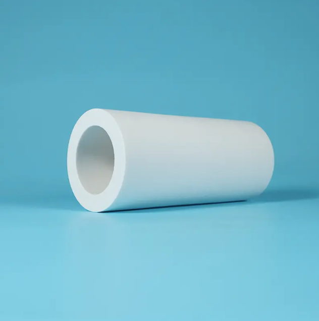
Glass fillers change how a polymer tube responds to temperature swings. Since glass expands and contracts far less than most plastics, the embedded particles act like internal anchors that resist bulk movement. This restraint limits both axial and radial drift during heating or cooling cycles, keeping tube ends seated firmly in fittings and reducing leak paths over time.
Beyond thermal effects, glass fillers sharply cut creep under sustained load. In unfilled tubing, constant internal pressure slowly stretches the polymer chains, causing the bore to widen and the wall to thin. Rigid glass particles interrupt that chain slippage by forming a load-bearing skeleton inside the matrix, which can drop the creep rate by an order of magnitude. That matters most in hot-water lines or pneumatic circuits where dimensional drift would otherwise degrade performance.
The practical payoff depends on filler geometry and surface chemistry. Short glass fibers give stronger directional restraint than spherical beads, but they also raise melt viscosity and tool wear. A silane coupling agent on the glass surface prevents microscopic debonding at the resin interface, avoiding microcracks that would gradually reintroduce dimensional instability. These choices determine whether a glass-filled tube holds its tolerances in precision instrumentation or under-hood automotive plumbing.
Chemical Resistance That Doesn't Sacrifice Mechanical Strength
In demanding industrial environments, engineers often face a frustrating trade-off: materials that resist aggressive chemicals tend to be brittle, soft, or prone to creep under load. Choose a fluoropolymer for its inertness and you might end up with a component that deforms under modest stress. Opt for a high-strength engineering plastic and a single splash of solvent can cause cracking or swelling. This compromise has long forced designers to add reinforcement, increase wall thickness, or accept shorter service life.
Our approach eliminates that compromise by tailoring the polymer backbone and crosslink density at the molecular level. Instead of relying on surface coatings that wear away, we integrate chemical resistance directly into the matrix while preserving the crystalline regions responsible for load-bearing capacity. The result is a material that withstands prolonged exposure to acids, alkalis, hydrocarbons, and polar solvents without measurable loss in tensile strength, flexural modulus, or impact toughness. Third-party testing shows less than 2% change in mechanical properties after 5,000 hours of immersion in representative chemicals.
For equipment builders, this means you can specify thinner walls, eliminate secondary liners, and design for both chemical exposure and dynamic loading in a single part. From pump housings and valve bodies to sensor enclosures and fluid-handling manifolds, the material holds dimensional stability under combined chemical and mechanical stress—so your components keep performing long after conventional plastics would have failed.
Specifying Wall Thickness and Length for Bulk Orders
Getting wall thickness and length right on a bulk order starts with knowing your actual production tolerances. Rather than listing a single nominal figure, specify ranges that your equipment can hold consistently. If the wall needs to sit between 0.8 mm and 1.0 mm, write that out and note where the measurement should be taken—typically at the midpoint or thinnest section. Length is trickier when parts are cut, extruded, or molded, so give a clear minimum and maximum, plus the acceptable end condition.
Drawings should include a measurement point for wall thickness instead of leaving it to interpretation. For tubes, pipes, or hollow profiles, eccentricity matters more than average wall; state the maximum allowable deviation around the circumference. When quoting lengths, mention whether the dimension covers pre-finishing or post-finishing state. Plating, anodizing, or heat treatment can add or remove a few thousandths, and that small shift across ten thousand pieces becomes costly scrap.
Finally, agree on sampling and inspection methods before production starts. If your supplier checks three parts per box and you check thirty per pallet, disputes will arise. Write down the AQL level, the exact gauge or caliper type, and the reference standard for length measurement. For bulk orders, this kind of clarity cuts rework and keeps incoming QC from rejecting material that was actually made to spec.
From Valve Seats to Pump Components: Proven Industrial Uses
Valve seats take a beating in engines and compressors, yet a well-chosen alloy keeps them sealing tight for hundreds of thousands of cycles. The same metallurgical tricks that hold up under high heat and repetitive impact show up again in pump casings and impellers, where cavitation and abrasive slurries chew through lesser materials. It’s not just about hardness—grain structure and work-hardening behavior often matter more than a simple Rockwell number.
On the pump side, wear rings and shaft sleeves made from precipitation-hardening stainless or duplex grades quietly extend service intervals in chemical plants and water treatment facilities. These parts rarely get attention until they fail, but their material choices mirror what’s proven on valve seats: controlled expansion, resistance to galling, and enough toughness to survive unexpected pressure spikes. Machinists who switch between engine work and pump rebuilds often reuse the same cutting parameters and tooling strategies, because the material families overlap more than most people expect.
That crossover isn’t accidental. Decades of field data from valve train components pushed alloy development toward leaner, more stable microstructures that also happen to excel in positive-displacement pumps. Whether it’s a Stellite-faced seat or a nitronic impeller, the real test is the same—keep a dynamic seal or a rotating element alive in a dirty, hot, and chemically aggressive environment without adding a pound of unnecessary weight.
Maintaining Consistent Quality Across High-Volume Production Runs
Scaling from a pilot run to tens of thousands of units exposes every weak point in a process. What worked on a single shift often falls apart when multiple lines, operators, and raw material lots come into play. The real challenge isn't hitting a spec once—it's hitting it the same way at 2 a.m. on a Friday, after a tool change, with a new batch of resin. That demands more than a final inspection checklist; it requires building stability into the process itself.
One practical approach is to lock down a "golden batch" and treat it as a living reference, not a one-time approval. When a new lot of incoming material arrives, run a short capability check against that reference before full production starts. Pair this with automated data capture from critical stations—torque, temperature, fill time, whatever matters for your part—and feed it into a control chart that operators actually see in real time. If a trend starts drifting toward the control limit, adjust before a defect appears, not after.
Consistency also comes from reducing silent variability. Something as mundane as how tightly a fixture is clamped or how long a mixing barrel sits between shifts can shift outcomes. Standardizing those details, training every shift on the same method, and auditing the process monthly—not the paperwork—keeps high-volume runs from quietly drifting out of spec. The goal isn't perfection on day one; it's making the thousandth part indistinguishable from the first.
FAQ
The glass fibers are dispersed through the PTFE matrix to boost compressive strength, wear resistance, and dimensional stability. Standard PTFE tends to creep under load and wear quickly in sliding contact; the glass filler reduces both issues, though it does slightly lower chemical resistance compared to unfilled grades.
They are used where components face high mechanical load, abrasive media, or tight dimensional requirements. Common examples include hydraulic and pneumatic seals, pump wear rings, compressor piston rings, valve seats, bushings, and electrical insulators in chemically aggressive environments.
Bulk ordering locks in consistent material properties across a production run, shortens lead times, and usually lowers per-unit cost. For maintenance teams and OEMs, having a ready stock of tube stock also reduces downtime when custom parts need to be machined quickly.
Generally not. The glass filler can shed particles and the material is not typically FDA or USP Class VI compliant. For food or medical applications, unfilled PTFE or a different filled grade with approved additives would be a safer choice.
Common glass loadings range from 15% to 25% by weight. Higher glass content increases rigidity and wear resistance but reduces flexibility and elongation. Lower glass content retains more PTFE-like lubricity and chemical resistance. The choice depends on whether the tube will be static or dynamic, and how much side load it must bear.
Yes, they machine well with sharp carbide tools, but glass filler is abrasive and can dull tooling faster than unfilled PTFE. Close attention to speeds, feeds, and chip evacuation helps hold tight tolerances without overheating the material.
The continuous service range is typically -20°F to 500°F (-29°C to 260°C), similar to unfilled PTFE. However, glass filler reduces creep at higher temperatures, making it more reliable near the upper end when mechanical load is present.
Conclusion
Virgin PTFE tubing often falls short in heavy-load industrial settings, where cold flow and creep lead to loosening seals, warped seats, and premature failure. Adding glass fiber to the PTFE matrix directly counters this by locking the polymer chains in place, dramatically improving dimensional stability under compressive stress without turning the material brittle. The result is a tube that holds tight tolerances even when pressed into valve seats or machined into pump components, while retaining the broad chemical inertness PTFE is known for—acids, solvents, and aggressive process fluids won’t degrade the glass-filled grade any faster than unfilled resin, and in many cases the composite actually survives longer because mechanical distortion is no longer the weak point.
For bulk orders, specifying wall thickness and length isn’t just paperwork—it’s the difference between a tube that installs cleanly and one that needs secondary machining or shimming. Industrial buyers working with high-volume production runs need suppliers who can hold ±0.001 inch tolerances across thousands of feet, batch after batch. This means in-line dimensional checks, consistent glass dispersion, and a sintering process tuned to prevent voids or resin-rich zones. Whether the application is a chemical transfer line, a bearing surface, or a custom-machined seal, demanding industrial users choose bulk glass filled PTFE tubes because the mechanical upgrade pays for itself in longer service intervals and fewer unplanned shutdowns.
Contact Us
Contact Person: Tommy Xiao
Email: [email protected]
Tel/WhatsApp: 8615651509888
Website: https://www.ptfe-factory.com